Overview
Lots of alliteration, I know- but this project really is pretty awesome! Plus, it is perfect for the Raspberry Pi Pico because it takes advantage of a few of it’s cooler features like running different tasks on each of its dual cores! There’s a ton to go through, so let’s dive right in!!!
Bill of Materials
NOTE: Many of the below links are affiliate links. These won’t cost you anything, but Ctrl Alt Develop will receive a small profit if you purchase through them. Please consider using these links if you’d like to support the blog so that we can provide even more content to you!
Below are the items I used in order to create this project. Keep in mind several of these purchases will provide you with additional parts that can be used for future projects as well!
- (x1) Raspberry Pi Pico Microcontroller
- (x3) Water Solenoid Valve
- (x1) Water Pump
- (x1) Hygrometer Sensors (5 pack)
- (x1) Level Shifters (6 pack)
- (x1) Mini Buck Converters (6 pack)
- (x1) 6 Channel Relay Board
- (x1) Electronics Enclosure – OPTIONAL
- (x1) Perf Board – OPTIONAL (can use breadboards instead)
- (x1) Grow Light
- (x3) Planter Troughs – OPTIONAL
- (x1) Female Power Jack (12 pack)
- (x1) Barrel Power Pigtail (10 pack)
- (x1) Heat Shrink Tubing (560 pcs)
- (x1) Bullet Connectors (100 pcs) – OPTIONAL
- (x1) Fuse Holder (5 pack) – OPTIONAL (but recommended)
- (x1) 4 Amp Fuse (10 pack) – OPTIONAL (but recommended)
- (x1) Solid Core Wire
- (x1) Stranded Power Wire – OPTIONAL
- (x1) Spade Connectors (100 pcs) – OPTIONAL
- (X1) Dupont Connector Set with Crimper – OPTIONAL
- (X1) 8 PIN JST Connector (8 pack) – OPTIONAL
- (x1) Male & Female Header Pins (30 pcs) – OPTIONAL
- (X1) Silicone Tubing
- (x1) Reverse Osmosis Filtrations Tubing and Connectors
- (x1) 3/16″ to 1/4″ adapter (5 pack)
- (x1) 19.5V 4.7A Power Supply
- (x1) Terrarium/Aquarium or other enclosure (I had one on hand so no link here)
- (x1) 1+ Gallon Water container (I used an empty bulk sized plastic pretzel container)
You’ll notice quite a few optional materials. Let’s just briefly go over these and why they are optional:
- Electrical Enclosure – While you don’t really need this enclosure, it would be good to have something to protect the components if you are going to make this a permanent working project.
- Perf Board – If you want to solder up a permanent version of this project, I would recommend this, but otherwise you could use a couple of breadboards and dupont wires
- Planter Troughs – You could use any planter container that will fit into your terrarium (or whatever you use as an enclosure).
- Bullet Connectors – These are for creating a disconnect for the water pump so that it’s easier to remove from the unit and refill in the sink.
- Fuse Holder and Fuse – These are to create an additional layer of safety. Between these, the computer charger’s on board protections and plugging into a surge protector, it might be overkill, but I’d rather be safe than sorry. We are dealing with water and power in close proximity, after all.
- Wires and Wire Connectors – The remainder of optional items are related to wiring and connections. Technically you could solder all of these connections, but using removable connectors helps with troubleshooting, modularity and mobility.
Finally, I should note that this project could be done even cheaper using electronics components like transistors and resistors to replace some of the pre-built components like the level shifters, relay board and buck converters, but using these components makes the build faster and easier.
Preparation and Tools
Tools
For a permanent version of this project you’ll need:
- Wire cutters
- Solder
- Soldering Iron
- Wire Strippers
- Multimeter
- Hot Glue Gun
- Needle Nosed Pliers
If you’re just breadboarding this, then all you need are a few breadboards and some various pre-made dupont wires (male to male, female to male and female to female). Though you might still want the wire cutters, strippers and soldering tools to hook up the power supply as well as the glue gun to hold your adjustable buck converters at the proper voltage.
Diagrams and Code
Wiring Diagram
Below is a pic of the wiring diagram:
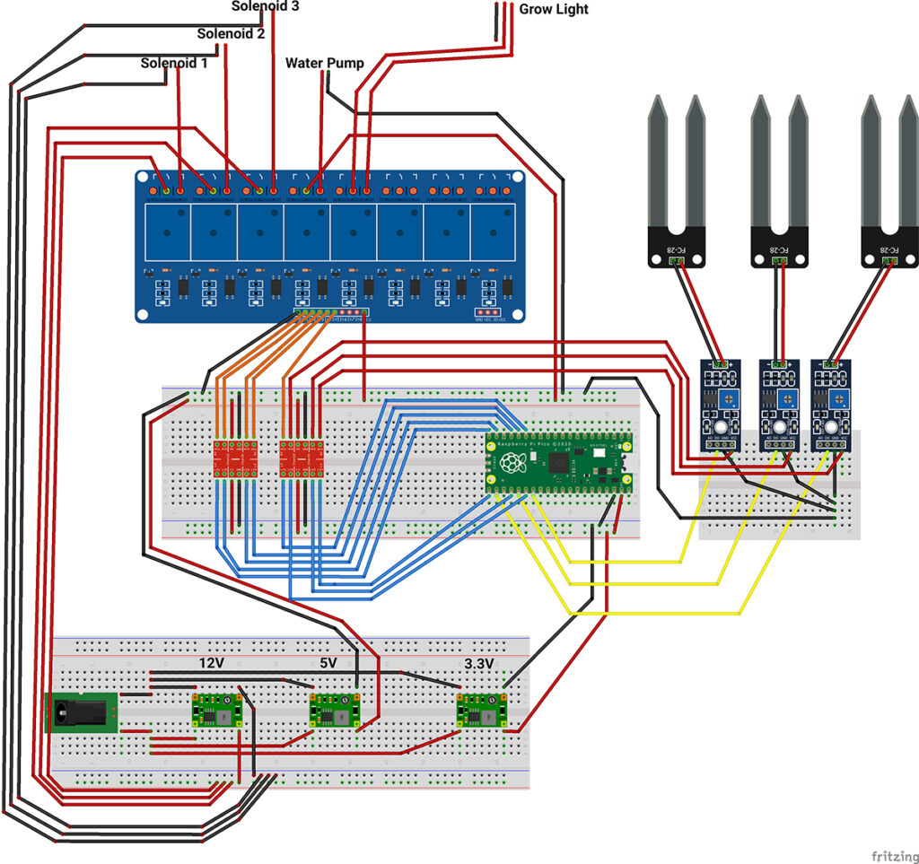
You can download this image for yourself here.
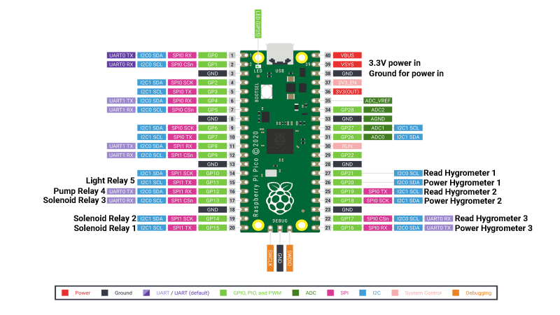
Below is another image… the pinout on the Raspberry Pi Pico:
Gotchas
You may notice in images of my perf board prototype further into this instruction set that the power for the Hygrometers are not running from the level shifters as shown above, but are running directly from the pins of the Pico. After testing, the 3.3V supply from the Pico and low current draw of these sensors will run from the pins of the Pico, but longer wire runs will create more resistance and drop the voltage to a point that the sensors don’t work quite right. For this reason and to increase the longevity of the Pico itself, I’d recommend wiring as described above.
On the relay, you’ll need a male to female DuPont wire, as those do actually connect directly to the board (notice there is no breadboard beneath that component).
Additionally, the relay board in the diagram shows 8 relays, but the parts list has a 6 channel relay. 6 is all you need, but I couldn’t find a 6 channel relay board as a fritzing part.
Finally, the grow light is confusing in this diagram, as it is run by a separate plug directly from the wall (AC) through the relay. We’ll get into the details of this later, so don’t stress. Once you see the photos, You’ll see that it’s pretty easy.
Code
The code for this project can be found on GitHub here:
https://github.com/DaveNadeau/automated_indoor_garden
The code can be viewed in the “watering_system.c” file. Hopefully you’ll find the code to be well commented but we’ll address a few points of note here as well…
Editing/Viewing the Code
If you want to edit the code and create a new executable, you’ll need to set up the Pico SDK and VS Code environment. There are lots of good tutorials on this, but it can take some time. The quickest and easiest way to get this all loaded and working on Windows is to use this script from github:
https://github.com/ndabas/pico-setup-windows
At the time of writing, this project is still being actively updated and is, in our opinion, the quickest way to start developing on the Pico outside of the standard Arduino environment. Hopefully the SDK will become easier to install and use as time goes on, but we can’t recommend this script enough for the time being!
Workflow
Essentially, The default setup of the code is as follows: once powered on, one core turns the light on and a delay is set for 16 hours. The light then turns off for 8. Rinse and repeat ad inifinitum.
On the other core, the hygrometers will be powered on briefly (this short power cycle is to limit the electrolytic effect on the sensors and thereby extend their lifespan) and will take a reading of the soil. Once the reading is reported back to the Pico, the program logic decides whether or not a watering cycle should be started, and which solenoids should be opened in order to water each trough (or plant) independently. If a watering cycle is needed, the water pump will also turn on. The watering cycle lasts 30 seconds and then the solenoids close and the pump turns off. A delay of 3 hours is started and the process starts all over at the end of that delay.
Multicore Coolness
You’ll see that we take advantage of the dual cores on the Pico to manage the lights completely separately from the watering cycle. While this could be done with a timer library on a single core, the dual cores make the process far easier to code as well as visualize.
Hygrometers – Digital or Analog
For this example project, it was decided that the precision of analog was not required, so the digital read was fine to use by adjusting the potentiometer. It also allows us to make general adjustments without having to pull out the pico and reprogram the point at which a watering cycle is triggered.
Switching to an analog reading is simply a matter of a code adjustment and moving the read pins on the pico to pins 26, 27, 28 and the other ends from the D0 to the A0 pins on the hygrometers. We will cover this in an updated version down the road, but for now we will use the digital output.
The Build
For this instruction set, we’ll be following the wiring diagram for the breadboard image. Many of the notes in here will be applicable to your build if you decide to build a more permanent version with perf board. We’ll also show a few images of our perf-board prototype at the end, but know that you can arrange the components on your perf board however it makes sense to you!
At any rate, it’s probably best to test all of your components on a breadboard first to ensure everything is working before you start soldering everything in place!
Power
Power Supply Modification
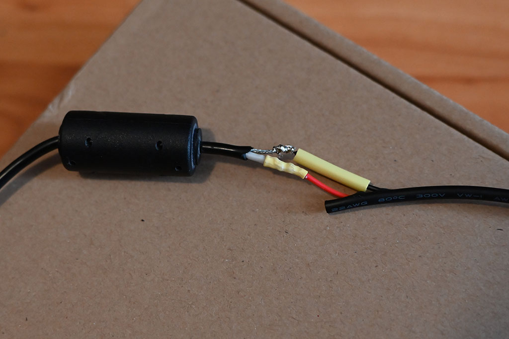
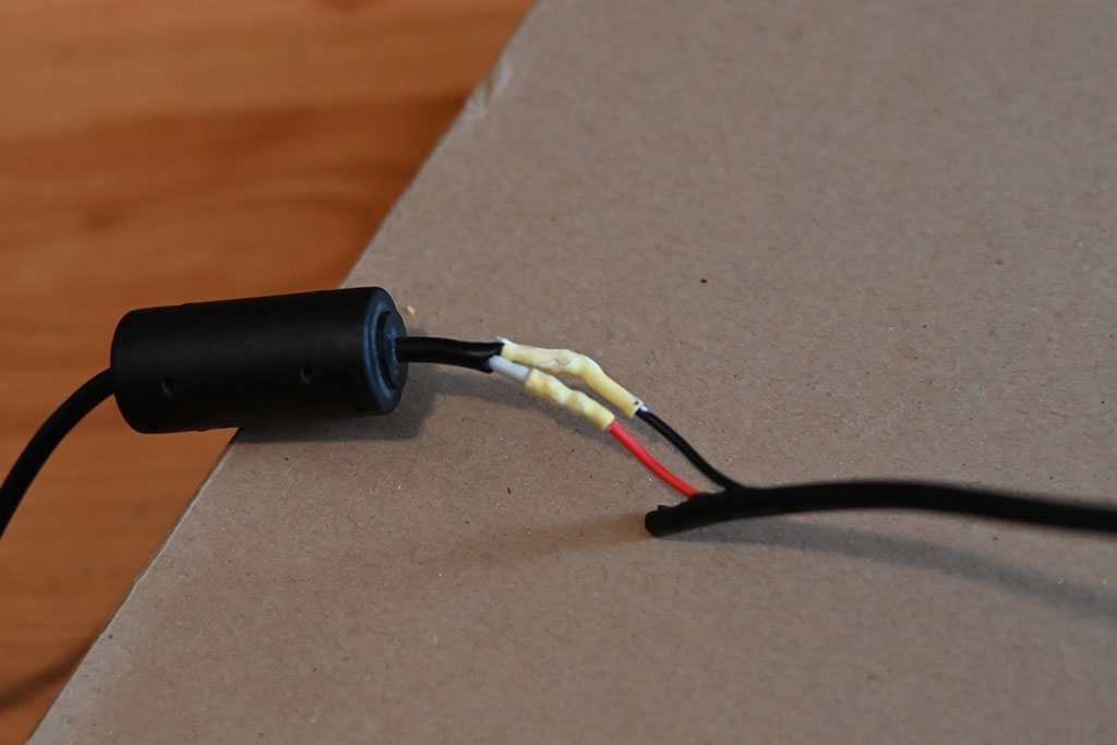
If you are using the parts outlined above, or similarly rated ones, using the computer power supply rated for 19.5 volts and 4.7 amps will supply plenty of power to all of the components (except the light- which has it’s own A/C power supply). To be able to use this – or any other power supply- you’ll need to clip the tip and replace it with the barrel connector that fits the female power jack you’ll be using. Typically the wires inside of the cord have their own coating (red for positive, black for ground/neutral). Wire the male pigtail red to red and black to black. If the wiring is not clear about which is which, leave the power supply unplugged, alligator clip your multimeter up to each wire (doesn’t matter which goes where). Make sure your multimeter is set to DC and reading volts. Now ensure that you are not touching the wires and plug in the power supply.
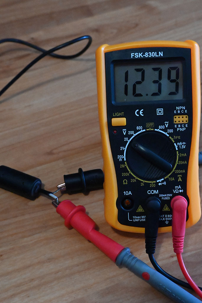
If the reading is a positive number, the Red clip is positive and the black is neutral. If it’s a negative number, the black is the positive and the red is neutral. Once identified, unplug the power supply and wait a bit. Often the supply has capacitors that will still hold power for a bit and shock you if you are not careful!
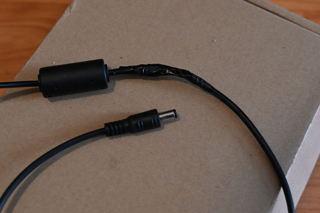
When ready, thread an end of wire through some heat shrink tubing, solder the wires together, then use the barrel of your soldering iron to shrink the tubing around the soldered joint. Finish with some electrical tape, or another heat shrink sleeve over the whole joint (you’ll have to put that larger heat shrink sleeve on before soldering anything).
Warning: You are dealing with DC current coming from mains power. This can be dangerous if you don’t know what you are doing. If you are not confident in your electrical knowledge or abilities, have someone help you or practice on lower volts/amps supplies. You are modifying this at your own risk… there. We’ve said it. You’ve been warned!
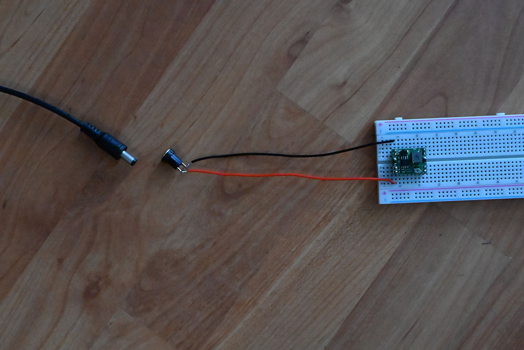
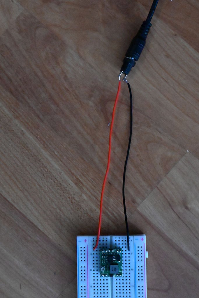
Anyway, for testing, you’ll want to cut a couple lengths of your solid core hookup wire, strip each end to about a half inch and run it through the holes on the female power jack and twist the end around itself to temporarily lock it into place. on the other ends, cut them down and bend them to 90 degrees so the the exposed wire can be completely put into the holes of a bread board.
Buck Converters
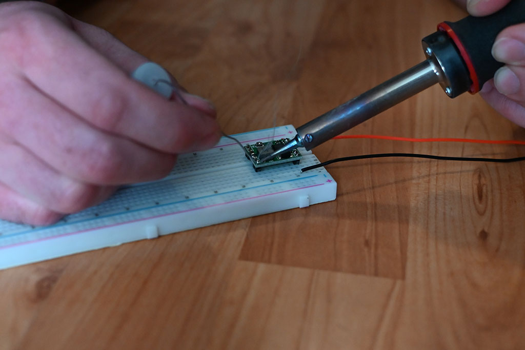
Per the diagram, you’ll need 3 buck converters; one at 12V, one at 5V and one at 3.3V. These come without the header pins, so you’ll need to solder them up. The buck converters don’t fit perfectly on a breadboard, so I’d put the header pins into the board halfway first, then wiggle the buck converter onto all of them and then solder while everything is held firm by the bread board.
After being soldered up, you’ll need to dial in the voltages for each converter. Before plugging the power supply into the wall, plug the barrel connector into the female jack and connect the jack to the breadboard:
Hook wires up to the output side of the converter and on the other end of those wires, connect the multimeter’s alligator clip leads to them. Make sure your multimeter is set to read DC volts. Now plug in the power supply to to wall. Using a small screw driver, use the tiny potentiometer on the buck converter to dial in the voltage while looking at the multimeter.
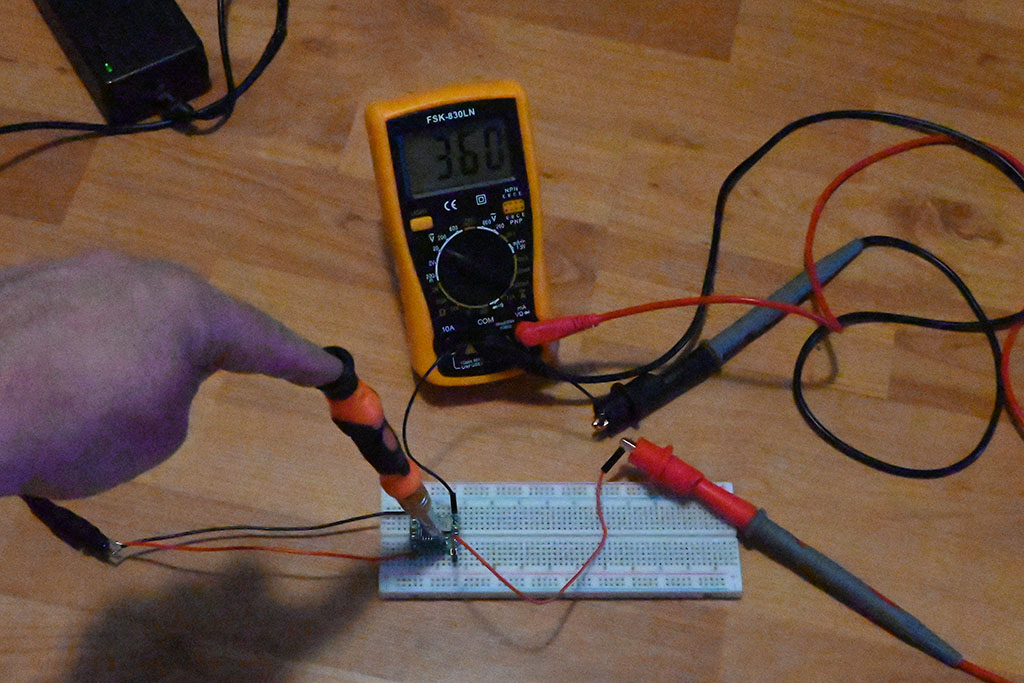
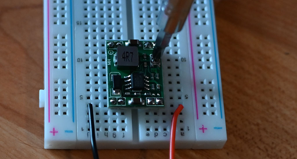
TIP: These buck converter adjustments are sensitive! Be patient and err on the side of just a bit too much voltage to counteract the natural resistance of the wires. Somewhere between .1 and .3 volts over should be fine. Also, use that hot glue gun to dab a bit of glue onto the potentiometer once you’ve dialed in your voltages. This will keep the dial from accidentally being turned.
Do this for each voltage and you’re ready to move on.
Level Shifters
The level shifters will go on a separate breadboard with the Pico. This is simply so that things are spaced out and easily visible in the diagram. If you can pack it all onto one or two breadboards, then by all means go for it!
Again, these level shifters do not have headers soldered to them, so that will be up to you to accomplish. Once complete, you’ll notice that these shifters get 2 different power inputs, one from 5V on the high side and one from 3.3V on the low side. Refer to the diagram and pinout images for the wiring of each of the signal pins to the relay and the hygrometers.
The 3.3V side will take the signal from the Pico and allow the corresponding circuit on the 5V side to close and allow power to pass to the relay board input pins or the hygrometer power pins, depending on which 3.3V pin is sending its signal.
Not much else to mention here. This covers the basic power and voltages.
Relay Board
We have now arrived at the relay board. We have opted for the simplest setup and power the board directly from the 5V power rail. There is another option to power from the opto LEDs from 3.3V and the actual relay coils from 5V by removing the jumper to the right and connecting to the JD-VCC and VCC pins. This is more complex, but offers full “opto-isolation”. While this is recommended in most settings, we have forgone this option in our prototype for the sake of simplicity. The only possible concern is the water pump and I have yet to have any problems with this setup.
However, if you’d like to learn more about this method, please read this.
For the relay, we go out to the solenoids, the water pump and the grow light. Let’s touch on each of these briefly.
Solenoids
From relays 1 through 3, you’ll be connecting your solenoid water valves. Notice that the 12V power goes to the middle terminal screw on that relay. On the relay board in the bill of materials, the left most terminal is normally closed (on by default) and the right most of the three terminals in each relay is normally open (off by default). Since our solenoid valves themselves are normally closed (won’t let water through), we want the relay to be normally open (not powered). How’s that for counter-intuitive, eh?
So the 12v supply goes to the middle terminal and the positive (typically red) wire goes from the right most screw terminal to one of the terminals on the solenoid- it does not matter which. You’ll notice the solenoids have spade connectors for terminals. While you can certainly solder the wire directly to these, it is recommended to crimp a spade connector onto the other end of the positive wire for easy connect/disconnect.
The neutral/black wire goes from the spade terminal on the solenoid directly back to the 12V power’s ground/neutral as shown in the diagram.
TIP: While it does not matter which terminal on the solenoid is hooked to positive or neutral, it DOES matter which way you hook the water lines to the solenoids, so be aware of the direction you wish the water to flow. More on this later.
Water Pump
The 5v pump we’ve selected in the bill of materials is a fantastic little pump! It is adjustable in its force and remembers the setting between power cycles and is more than adequate to pump water to 3 lines. Just like the power supply, we snipped off the usb power connector.
In the diagram above, you’ll note the 5v supply on the Pico/level shifter bread board goes to the 4th relay, middle screw terminal. The neutral wire on the 5V rail goes out to meet the neutral wire from the pump while the right most screw terminal of on the relay has a wire that goes out to meet the positive wire of the pump. On the ends of the pump wires and the open ends of the wires from ground (-) and relay (+), you could solder these together for a permanent bond, but that makes refilling the water tank a real problem.
Instead, we’d recommend using the bullet connectors like so:
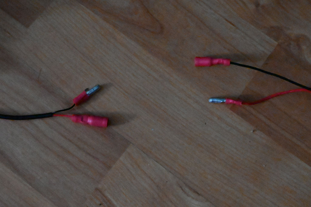
TIP: To ensure you don’t accidentally connect the wires incorrectly, crimp opposing ends of the bullet connectors onto each wire of the pump supply as shown in the image. This makes it impossible to accidentally connect positive to neutral and vice versa! Also, when first fitting the connectors, you may need to wiggle them back and forth to loosen the connection enough to be able to connect and disconnect them without pliers each time!
Grow Light
Since the grow light has its own built in DC conversion and draws a lot of power (comparatively speaking), we decided to keep the power supply separate on this and only create a switch with the relay. As we said previously the diagram is not very clear, so please see the images and descriptions below.
As you can see the, power cord was cut and the outer sheath peeled back so we could see the actual wires. The positive wire on the plug side goes to the middle screw terminal on relay 5, while the positive wire on the light side of the cord goes to the right-most (normally open/off) screw terminal. Technically the neutral wire doesn’t need to be cut at all, but in practice that was difficult to do and would’ve complicated the electrical enclosure wiring, so we just cut the entire cord and re-soldered the neutral wire back together.
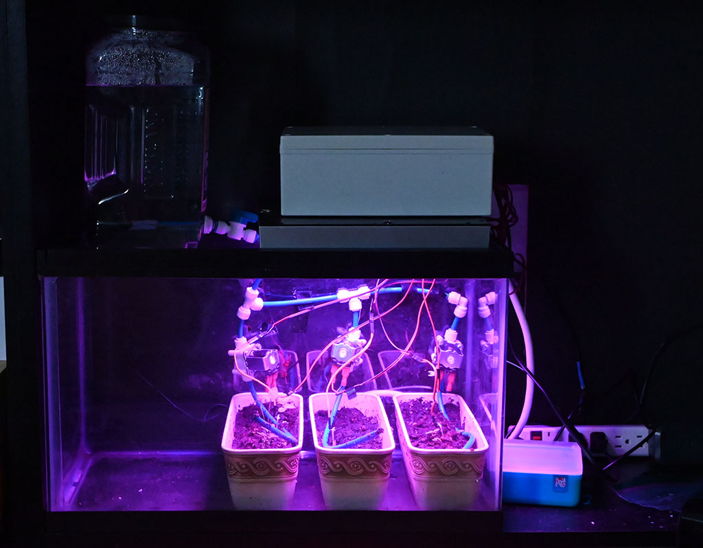
When completed, the light simply rests on the top of the terrarium with the electrical enclosure on top of that.
Hygrometer Sensors
The last real component of the system is the set of hygrometers. One for each growing trough (or zone, if you will), this setup allows for vegetation of different “thirsts” to all be placed in different growing zones and be sated to their liking.
As noted earlier, using the pins on the Pico is possible, and in fact is being temporarily the case on our v1.0 prototype board. However, the 3.3V is the bare minimum for these sensors and any long length of wire begins to impede the signal. Because of this, the diagram shows the wiring going through the level shifter to power the device. Since we are using the digital output, worrying about analog reads and conversion is avoided and the digital read goes directly back to the input pins of the Pico since even when powered at 5 volts, the digital out pin only sends about 2.6 volt signal back to the input pins on the pico, which is well below the 3.3V threshold.
Watering System
The tubing we went with was for a reverse osmosis (RO) filtration system. We chose this because it had easy quick connect junctions, could easily be drilled or pierced with hot metal to create watering holes, could be “capped” by heating the ends with a lighter while being squeezed by pliers, and could be molded to fit around the troughs with a heat gun. Additionally, the tubing worked with a bulkhead and valve for the water containter.
The pump, however, had a different sized outlet, so we had to get a second larger sized silicone tube and a barbed hose adapter to go down in size to the RO tubing.
Water container
The Water container could be anything you want, but the idea behind it was to have something that was big enough to hold a decent amount of water (so as not to be refilled too often) while still being able to sit on top of the terrarium so that gravity could help with the water delivery.
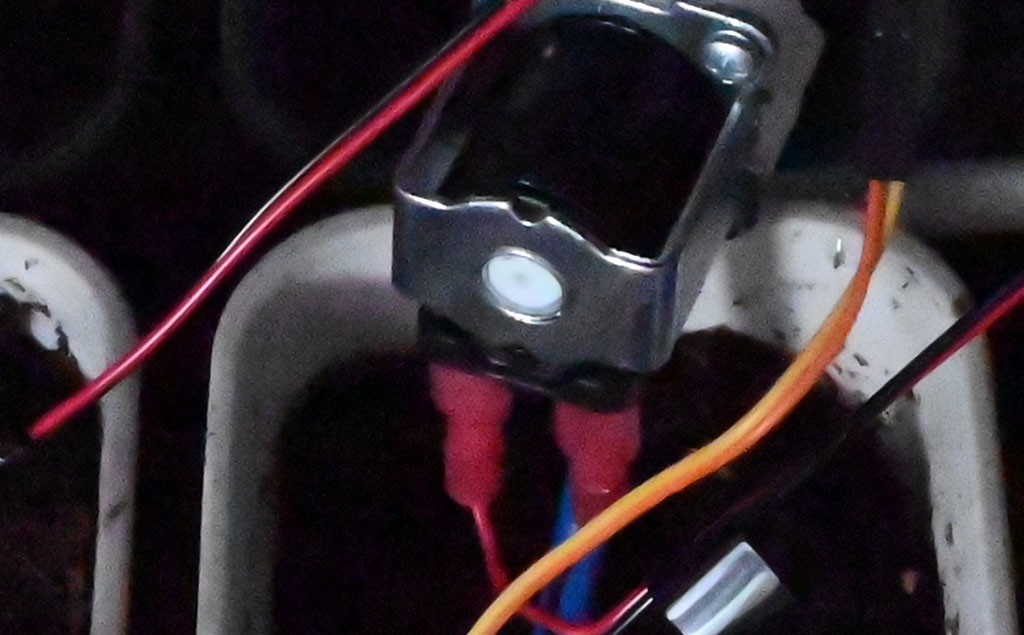
Initially we wanted a thicker tupperware style container, but drilling into the side we placed too much pressure and cracked it. So we had to improvise…
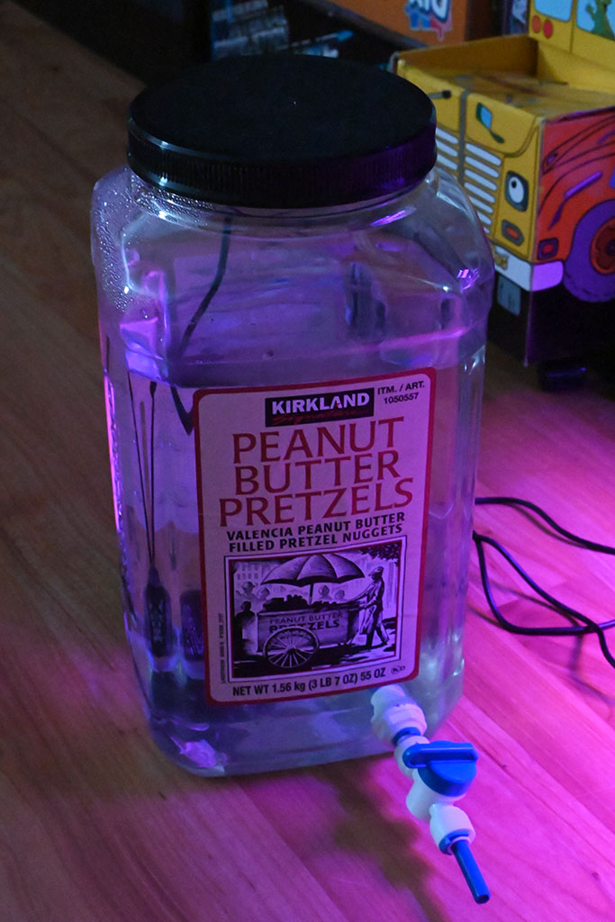
You’ll notice the hole drilled into the side and the bulkhead (with valve) attached. We used some silicone caulking around both the bulkhead and the lugnut (threaded washer?) on the inside and then tightened it down and removed the excess and let it dry for 24 hours.
From there, plug in a small bit of RO tubing, then the hose adapter, and finally the larger silicone tubing to from the adapter to the output of the pump. Also cut out a small notch or perhaps drill a hole in the upper portion of the container to push the pump’s power wire through. If you go with drilling a hole, don’t put the bullet connectors on until after you feed the wires through the small hole, then fill the hole with caulk and let dry.
Water Tubing
From the valve, the RO and quick connections branch out to feed each trough. Be sure to put the solenoid valves above the planters and make sure they are going in the right direction! about an hour and a half of the build time was spend troubleshooting why only one valve was opening no matter what and only barely leaking into its planter… only to discover that the valve was put in place backwards! You’ve been warned!
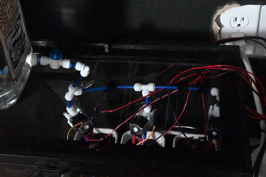
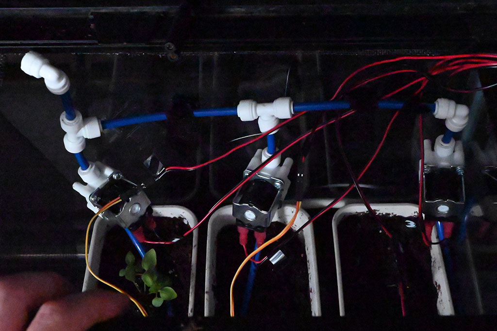
Given the modularity of the RO tubing and quick connect system, the image above is really only a suggestion. Feel free to modify it however will work most efficiently for your setup.
The holes in the “sprinkler tubes” (more RO tubing) were made by molding them into an appropriate shape by applying a heat gun at point that needed to be bent into an appropriate shape (use gloves or oven mitts!). Once you’re happy with the shape, make the holes by heating a small bit of metal (for us it was a bit of a binder clip, but an awl or large needle would work well, too) with a lighter while holding it with pliers. When red hot, press into the RO tube until you’ve pierced to the center of the tube- you’ll feel it when it happens.
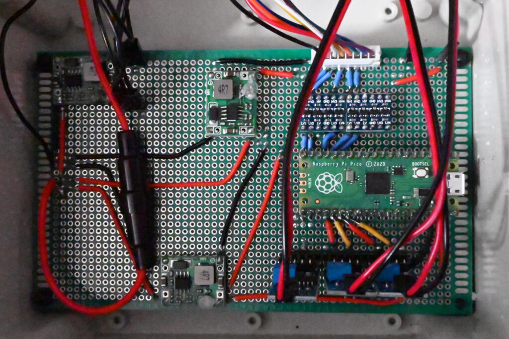
Perf Board Permanence
If you are interested in this project as a long term household appliance, we would recommend soldering all of this to a perf board. There are endless ways to go about arranging these components onto a perf board, and the images below are only a demonstration of one way of doing it.
In order to get an idea of how to lay this out and how to wire it, we used a printed “diagram” of a perf board- which is basically just a sheet of perfectly spaced circles printed on a sheet of paper- and started drawing our wiring and components on it. The “diagram” is a PDF that can be downloaded here.
No plan survives the enemy, though, and our perf board diagram didn’t end up perfectly matching the execution, mainly due to sub-par soldering skills. Despite the inconsistencies, we found planning the layout on paper to be an invaluable exercise and recommend it highly.
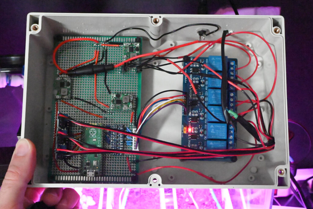
Poor soldering skills aside, the perf board allowed us to fit everything (relatively) neatly into the enclosure. We also used standoffs to keep the board and wiring from shorting due to bumping or jarring.
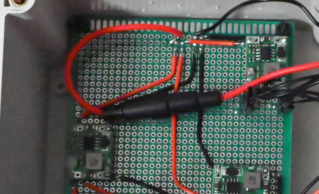
For added safety in the permanent version, we wired an inline fuse from the barrel connector to the board. The fuse is rated for 4 amps, while the power supply is 4.7 amps, so we are further limiting current. We also plug this into a surge protector instead of directly into the wall.
The enclosure itself is waterproof as well, but since we drill a hole in the side it is technically compromised.
Final Thoughts
There is a lot to try and squeeze into this tutorial, and there are some things I’m sure I’ve left out. But part of the fun of these projects is the process of troubleshooting and problem solving! Of course, when it stops being fun and you still can’t figure out what is going wrong, you are immediately in your own personal hell- but that is also part of the journey!
Speaking of, I’d like to send out a big thank you to Rick Nadeau, who patiently stood by my side while I was “troubleshooting” the leaky and non-functioning solenoid valves… after a couple hours with a multimeter and tearing the project apart, we finally realized that I’d put the darn solenoids on backwards! Regardless, we were triumphant and you can see in a couple of the above photos a few seedlings sprouting as proof!
One thing I will note is the the wires inside of the terrarium could definitely use some sprucing up. I’ll likely run the wiring along the water supply lines or pin them to the back somehow so the sprouting plants don’t get tanlged in them.
Care to try your hand at the project? Dive in! If you have any questions, ask them in the comments and we’ll help in any way we can!
Thanks for reading!


Pingback: Facebook Outage, Now Azure is down… What’s Next??? – Ctrl Alt Develop
Pingback: 7 Desktop Gardening Projects for Arduino and Raspberry Pi - usa news
Pingback: 7 Desktop Gardening Projects for Arduino and Raspberry Pi – Mass Blog
Pingback: 7 Desktop Gardening Projects for Arduino and Raspberry Pi – Gaudhulimon.xyz
Pingback: 7 Desktop Gardening Projects for Arduino and Raspberry Pi – Nazmul Marketer
Pingback: 7 Desktop Gardening Projects for Arduino and Raspberry Pi – Best Soundcloud Rappers 2019
Pingback: 7 Desktop Gardening Projects for Arduino and Raspberry Pi | West Observer
Pingback: 7 Desktop Gardening Projects for Arduino and Raspberry Pi - Celeb News Live
Pingback: 7 Desktop Gardening Projects for Arduino and Raspberry Pi - PiShop Blog
Pingback: 7 Desktop Gardening Projects for Arduino and Raspberry Pi
Pingback: 7 Desktop Gardening Projects for Arduino and Raspberry Pi - OnlinePixelz
Pingback: 7 Desktop Gardening Projects for Arduino and Raspberry Pi – teknologi
Pingback: 7 Desktop Gardening Projects for Arduino and Raspberry Pi – MUO – MakeUseOf – Ceck an App Builder
Pingback: 7 Desktop Gardening Projects for Arduino and Raspberry Pi - Tausi Insider
Pingback: ▷7 projets de jardinage de bureau pour Arduino et Raspberry Pi ✔️ lizengo.fr - 【 2022 】
Pingback: 7 个适用于 Arduino 和 Raspberry Pi 的桌面园艺项目 – TECNO ID